|
Idaho Amateur Radio Emergency Service |

|
|||||||||||||
|
|||||||||||||||
|
|
Idaho Amateur Radio Emergency Service |
|
|||||||||||||
|
|||||||||||||||
Some organizations or groups conduct structured digital communications, using FLDIGI, and may provide a set of FLDIGI Macros to support their digital communications activities. This article intends to provide some guidance on how to locate the FLDIGI Macro folder, and then how to configure FLDIGI to use the newly installed macro file.
On Windows, navigate to:
C:\Users\YOUR_ACCOUNT_NAME\fldigi.files\macros
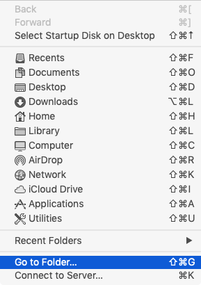
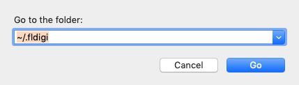
On Mac OS, the FLDIGI configuration data folder is hidden. You can navigate to the macro file by executing the following steps:
Why not just use AutoCAD or SolidWorks?
| Feature | Hagercad | General CAD (AutoCAD/EPLAN) | | :--- | :--- | :--- | | Cost | Free | High licensing fees | | Hager Library | Built-in, automatic | Manual creation required | | Part Numbers | Automatically assigned | Manual lookup needed | | Thermal Calc | Integrated | Requires external spreadsheets | | Output | Panel layout + Schematic + BOM | Usually one focus area |
For a contractor who exclusively or primarily uses Hager gear, Hagercad is the most efficient tool. Generic software forces you to be an IT specialist and a librarian; Hagercad allows you to remain an electrician.
As you design, HagerCAD generates a live BOM. This list updates in real-time as you add or remove components. Crucially, the BOM exports directly to ERP systems or purchasing spreadsheets. It includes Hager part numbers, descriptions, quantities, and even suggested order codes for accessories like mounting rails or terminal blocks. hagercad
If you are new to the software, here is how a standard project flows from start to finish:
Step 1: Project Creation You start by naming your project and selecting the standard you are working to (e.g., IEC, NF, VDE). This sets the symbol libraries and wiring color codes.
Step 2: Single Line Diagram (SLD) You build the main power distribution. Drag a main switch, add feeders, and assign protective devices (Circuit breakers, fuses). Hagercad calculates the short-circuit current based on the upstream values you input. Why not just use AutoCAD or SolidWorks
Step 3: Multi-Line Schematics Here is where you add control circuits. Place relays, contactors, timers, and PLCs. Use the auto-connect feature to draw wires. The software automatically numbers the wires based on your logic (e.g., L1, L2, L3, +24V).
Step 4: Panel Layout (Physical View) Switch to the "Cabinet" module. Select your enclosure (e.g., Hager Vector SFB). The software shows you the mounting plate. Drag the components from your schematic into the physical view. The software snaps them to DIN rails and ensures screw hole alignment.
Step 5: Thermal Check & Validation Hit the "Simulate" button. Input the ambient temperature (e.g., 35°C in a boiler room). The software turns red for zones that are overheating and suggests a ventilation fan or a larger enclosure. As you design, HagerCAD generates a live BOM
Step 6: Export Generate your BOM, print your wiring labels, and export the schematic as a PDF for the client.
The heart of Hagercad is its exhaustive database. When you select a circuit breaker, a residual current device (RCD), or an enclosure, you aren’t just drawing a box—you are selecting a specific Hager SKU. The software automatically pulls the physical dimensions, connection points, and technical specifications for that item. This "single source of truth" prevents the common mistake of designing a panel that is too small for the required components.